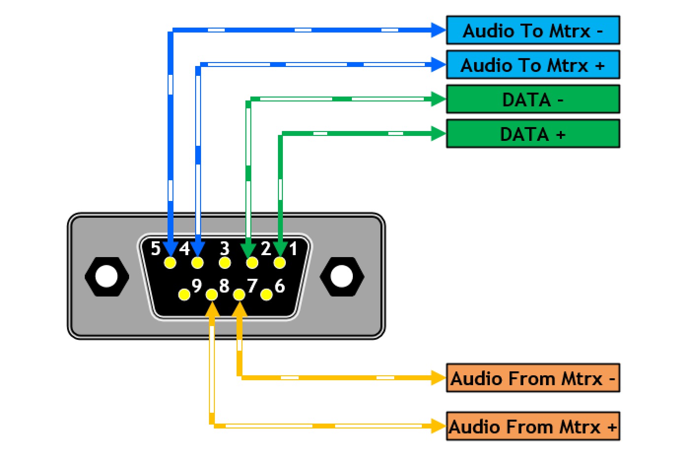
Db9 Pin Color Code
Lead Color: DB9 Pin Number: DTE Function: Black: 1: DCD: White: 2: RD: Brown: 3: TD: Red: 4: DTR: Yellow: 5: GND: Green: 6: DSR: Blue: 7: RTS: Purple: 8: CTS: Gray: 9: RI: Clear: Shell: GND. A DB9 clearly has 9 connections and a cat5(e) cable has 8 conductors. RS232D has chosen to use Pin 1 as a multi-function pin (DSR/RI) to provide maximum flexibility with modems - in particular it allows for DCD which is a meaningful signal from a modem but not we suggest from a peer PC. We have chosen to use a minor variation on the normal DB9.
The DE-9 D-sub 9-pin connector is often mistakenly referred to as the'DB-9' connector. The 'E' refers to the shellsize. A 'DB-25' connector has a 'B' size shell, butthe common nine-pin connector is smaller and has an 'E' sizeshell.
This connector (regardless what you call it) is used for a variety of purposes. Two commonapplications are RS-232/EIA-232 (serial) connections (including UPS cables), and avariety of video interfaceson the IBM PC.
Here's a good set of figures for D-sub 9 male and female connectors, as viewedfrom the pin side (not the solder side).
D-sub 9 Male
D-sub 9 Female
Pins commonly used for RS-232/EIA-232 (serial):
| DB-25 | D-sub-9 | Signal Direction | Signal Name |
| 1 | x | Protective Ground | |
| 2 | 3 | DTE-to-DCE | Transmitted Data |
| 3 | 2 | DCE-to-DTE | Received Data |
| 4 | 7 | DTE-to-DCE | Request To Send |
| 5 | 8 | DCE-to-DTE | Clear To Send |
| 6 | 6 | DCE-to-DTE | Data Set Ready |
| 7 | 5 | x | Signal Ground |
| 8 | 1 | DCE-to-DTE | Received Line Signal Detector (Carrier Detect) |
| 20 | 4 | DTE-to-DCE | Data Terminal Ready |
| 22 | 9 | DCE-to-DTE | Ring Indicator |
Click here to see the pinout of DB-25connectors.
| Signal Name | DB-25 Pin | D-sub 9 Pin | D-sub 9 Pin | DB-25 Pin | ||
| FG (Frame Ground) | 1 | - | X | - | 1 | FG |
| TD (Transmit Data) | 2 | 3 | - | 2 | 3 | RD |
| RD (Receive Data) | 3 | 2 | - | 3 | 2 | TD |
| RTS (Request To Send) | 4 | 7 | - | 8 | 5 | CTS |
| CTS (Clear To Send) | 5 | 8 | - | 7 | 4 | RTS |
| SG (Signal Ground) | 7 | 5 | - | 5 | 7 | SG |
| DSR (Data Set Ready) | 6 | 6 | - | 4 | 20 | DTR |
| CD (Carrier Detect) | 8 | 1 | - | 4 | 20 | DTR |
| DTR (Data Terminal Ready) | 20 | 4 | - | 1 | 8 | CD |
| DTR (Data Terminal Ready) | 20 | 4 | - | 6 | 6 | DSR |
Click here to see the pinout of DB-25connectors.
D-sub 9 pins commonly used for the IBM-PC CGA (color) video:

| Pin | Description |
|---|---|
| 1 | Signal ground |
| 2 | Signal ground |
| 3 | Red video |
| 4 | Green video |
| 5 | Blue video |
| 6 | Signal intensity |
| 7 | Unused |
| 8 | Horizontal sync |
| 9 | Vertical sync |
Click here to see the pinout ofHD-D-sub15 connectors (used for VGA).
D-sub 9 pins commonly used for the IBM-PC EGA (color) video:
| Pin | Description |
|---|---|
| 1 | Signal ground |
| 2 | Secondary red |
| 3 | Red video |
| 4 | Green video |
| 5 | Blue video |
| 6 | Secondary green / signal intensity |
| 7 | Secondary blue / Monochrome |
| 8 | Secondary blue / horizontal sync |
| 9 | Vertical sync |
Click here to see the pinout ofHD-DB-15 connectors (used for VGA).

D-sub 9 pins commonly used for the IBM-PC MGA/HGA (monochrome) video:
Color Code From Image
| Pin | Description |
|---|---|
| 1 | Signal ground |
| 2 | Signal ground |
| 3 | Not used |
| 4 | Not used |
| 5 | Not used |
| 6 | Signal intensity |
| 7 | Video signal |
| 8 | Horizontal sync |
| 9 | Vertical sync |
Db9 Pin Color Code Hex
D-sub 9 pins sometimes used for VGA (color) video:
| Pin | Description |
|---|---|
| 1 | Red Video |
| 2 | Green Video |
| 3 | Blue Video |
| 4 | Horizontal Sync |
| 5 | Vertical Sync |
| 6 | Red Ground |
| 7 | Green Ground |
| 8 | Blue Ground |
| 9 | Sync Ground |
Db9 Cable Color Code
Click here to see the pinout ofHD-D-sub 15 connectors (used for VGA).
